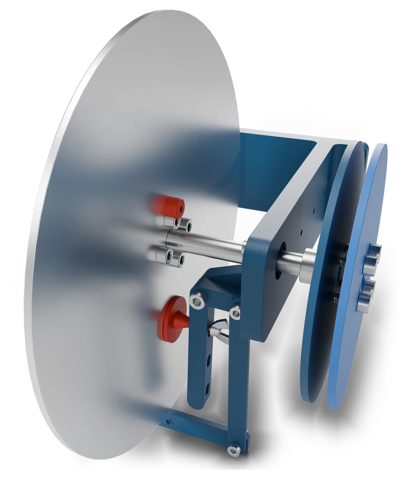
Experimental apparatus for disc-brake friction torque
A bench-top model of an automotive disc brake. A brake pad is pressed against a rotating stainless-steel disc by a pair of bell-crank levers loaded with calibrated weights; a cord and pulley on the shaft apply the driving torque, and a 360° protractor records the disc rotation. By changing the pad material and its radial position on the disc, students relate the normal force, the friction radius and the coefficient of friction to the resulting braking torque.
Experiments
Relationship between braking force, braking torque and normal force
Effect of the brake-pad material (coefficient of friction):
Brake material, aluminium, brass and nylon pads compared
Effect of the radial position of the pad (friction radius) on the braking torque
Determination of the most effective pad material and placement
Description
A stainless-steel disc turns on a shaft carried by wall-bracket supports. A small circular brake pad is held against the disc by two bell-crank levers; calibrated weights on the levers set the normal force, while a cord wrapped around a pulley on the shaft applies the driving torque through a load hanger. A 360° protractor reads the angular position of the disc. The pad can be fitted in different materials and clamped at several radii, so the braking torque can be related to friction radius, normal force and the coefficient of friction.
1
Brake pad
2
Stainless-steel brake disc
3
Cord pulley
4
Wall bracket
5
360° protractor
6
Bell-crank lever
Disc & pad
Brake discstainless steel, ø 210 mm, 3 mm thick
Brake padø 25 mm, up to 6 mm thick
Pad materialsbrake material, aluminium, brass, nylon
Radial positionsadjustable at 20 mm intervals
Loading & measurement
Levers2 bell-crank
Protractor360°, 1° increments
Load hangers2
Weight set3 × 0.1 N · 8 × 0.2 N · 3 × 1 N · 3 × 2 N · 1 × 5 N