All products

FM351 · Flow Meter Calibration

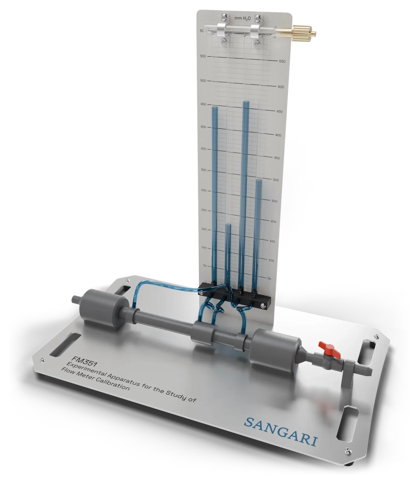
Experimental Apparatus for the Study of Flow Meter Calibration

Learning objectives / experiments
  • Determination of the accuracy of each flow meter, such as:
    • Nozzle
    • Venturi
    • Sharp-edged orifice
    • Pitot tube
  • Determination of the coefficient of discharge of each flow meter
  • Determination of the pressure loss and of the k value of each flow meter, referred to the straight pipe
  • Study of the effect of a constriction on the pressure in a pipe
  • Measurement of the velocity profile across the pipe with the Pitot tube
  • Study of the boundary layer and of surface friction in pipe flow
FM351
Description
    The FM351 is a short pipe run on a base plate, open in the middle between two quick-change adaptors. Any of the five flow elements drops into that gap and locks without tools. Four water manometers on the panel behind the run show the pressure across the element and across the whole flow meter assembly. A ball valve downstream sets the flow rate. The apparatus works on our FM500 hydraulic bench or on any laboratory bench.
The FM351 apparatus with its parts named
Hand pump connection
Used for setting the datum of the manometer tubes
Four water manometers
Pressure tappings
Inlet
Flexible hose from hydraulic bench
Quick-change flow meter adaptors
Flow meter
Different flow meters can be easily installed, without the need for tools
Flow control valve
Outlet to the hydraulic bench
The FM351 apparatus with its parts named
Hand pump connection
Used for setting the datum of the manometer tubes
Four water manometers
Pressure tappings
Inlet
Flexible hose from hydraulic bench
Quick-change flow meter adaptors
Flow meter
Different flow meters can be easily installed, without the need for tools
Flow control valve
Outlet to the hydraulic bench
Software
  • hydraulic data management software, supplied with the apparatus
  • simple to use, with clear options for displaying the data
  • records every reading and calculates the flow rate, the coefficient of discharge and the k value
  • exports the charts and the results for the report
Main characteristics
  • quick-change adaptors and pressure connections, so flow meters change without tools
  • five flow elements supplied, nozzle, Venturi, sharp-edged orifice, Pitot tube and straight pipe
  • four water manometers on a common manifold with air valve and hand pump
  • Pitot tube with micrometer head traverse and wall tapping for the static pressure
  • straight pipe for comparing the true pressure losses of the flow meters
  • flow control valve downstream, so the flow reaches the meter undisturbed
  • works on the worktop of our FM500 hydraulic bench and of any laboratory hydraulic bench, on a hose connector
Technical specifications
    Operating environment use in the laboratory
    Operating temperature +5…+40 °C
    Operating relative humidity 80 % at temperatures below 31 °C, decreasing linearly to 50 % at 40 °C
    Net dimensions W 760 × H 745 × D 450 mm
    Weight approx. 12 kg
    Flow elements 5, interchangeable, each 340 mm between the adaptor faces
    Nozzle flow meter profiled nozzle
    Venturi flow meter converging cone, throat and diverging cone
    Orifice flow meter sharp-edged plate
    Pitot tube micrometer head traverse, wall tapping for the static pressure
    Straight pipe plain bore, the reference for the true losses
    Manometers 4, water-filled, 16 mm bore, common manifold with air valve and hand pump
    Manometer scale printed on the panel, 0…600 mm water
    Pressure tappings 4, two across the flow meter and two across the flow meter assembly
    Flow control ball valve downstream of the flow meter
    Bench connection hose connector, to the FM500 or any laboratory bench

Scope of delivery
  • 1 FM351 apparatus, with the four water manometers, their manifold and the downstream ball valve
  • Included flow elements:
    • Nozzle flow meter
    • Venturi flow meter
    • Sharp-edged orifice flow meter
    • Pitot tube with micrometer head and wall tapping
    • Straight pipe, for the loss reference
  • 1 hand pump for the manometer manifold
  • 1 set of hoses for the hydraulic bench connection
  • 1 hydraulic data management software licence
  • 1 set of instructional material with the experiment procedures

All components and accessories listed under Scope of delivery are supplied, whether or not they are visible in the illustrations.