Experimental Unit for the Calibration of Electronic Pressure Sensors
A self-contained benchtop apparatus for calibrating an electronic pressure sensor against a dead-weight piston manometer - a true primary pressure standard - with a cutaway sensor model for
teaching the internal construction.
Description
The apparatus demonstrates the calibration of an electronic pressure sensor against a true primary standard. The reference pressure is generated with a dead-weight piston manometer: a piston of
known cross-section is loaded with graduated weight rings, so the test pressure follows directly from p = F/A - five weights produce graduated pressures from 0.5 to 2.5 bar in
0.5 bar steps. Hydraulic oil transmits the pressure to the diaphragm of the sensor under calibration; rotating the piston during measurement minimises the influence of friction, and a
hand-operated pump with relief valve returns the piston to rest after each reading.
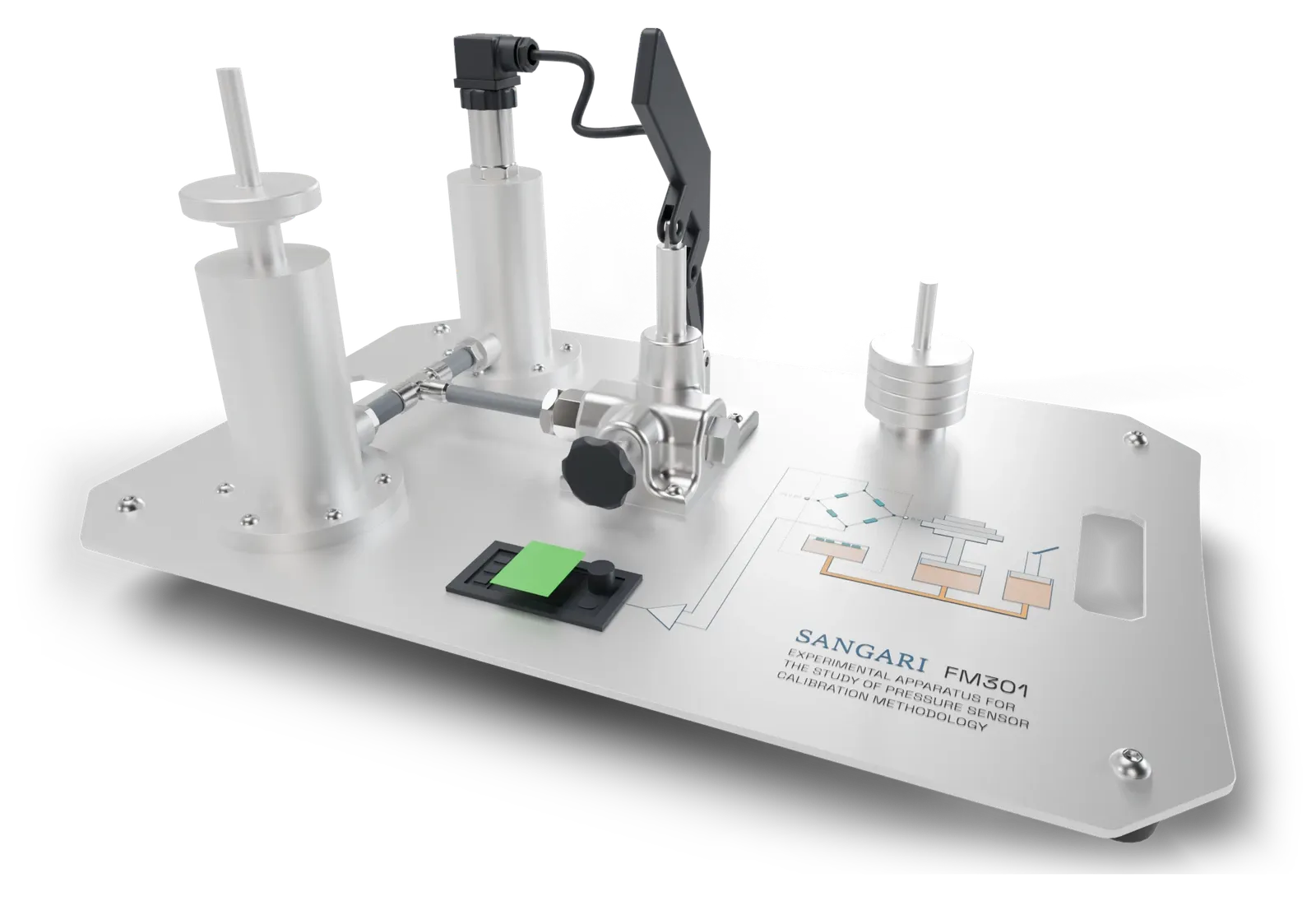
Top view of the FM301 experimental unit
Top view of the FM301 experimental unit
1
Pressure sensor to be calibrated
2
Stainless steel pipes
3
Dead-weight piston manometer
4
Set of weights
5
Hand-operated hydraulic pump
6
Process schematic
7
Digital display
Top view of the FM301 experimental unit
Experiments
Calibration of an electronic pressure sensor under practical conditions
Generation of reference pressures with a dead-weight piston manometer
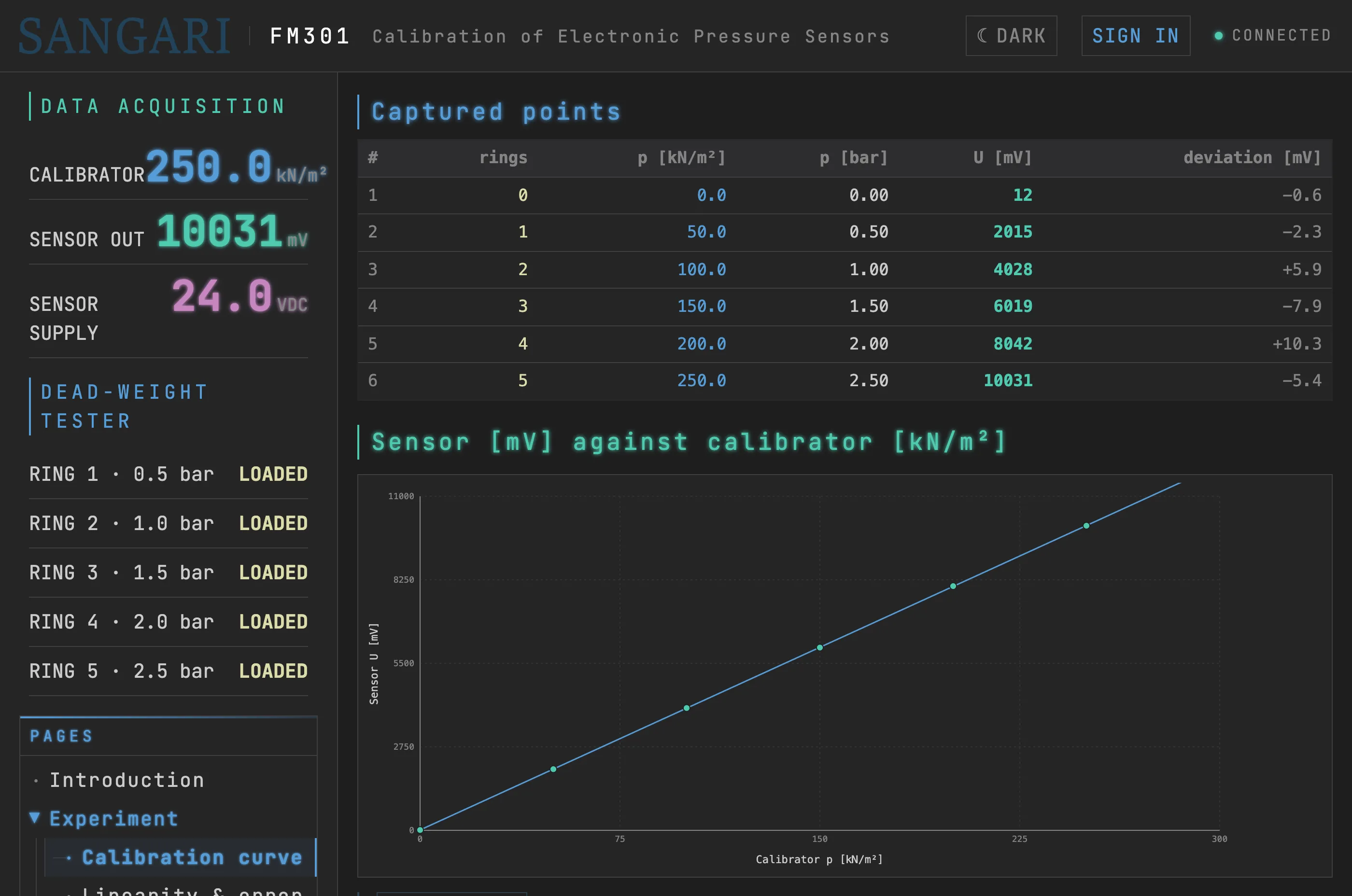
Plotting the sensor output signal as a function of the applied pressure - the calibration curve
Design and operation of a piezoresistive pressure sensor with ceramic measuring cell
Installation and electrical connection of pressure sensors
Applications, measuring ranges and accuracies of typical electronic pressure sensors
230V
22kg
Software
FM301 Software screen
Sensor and Evaluation
The sensor under test is a modern piezoresistive transmitter: strain-dependent piezoresistors on a ceramic diaphragm are wired as a measuring bridge, and an integrated amplifier converts the
bridge detuning into a proportional voltage output shown on a 4½-digit digital display. Students plot output signal against applied pressure to obtain the calibration curve. A second, sectioned
pressure sensor reveals the internal construction - ceramic measuring cell, sealing ring, pressure connection and equalisation bore. The unit is fully self-contained, with the process schematic
printed on the front panel; only a mains connection is required.
Specifications
Pressure sensorceramic measuring cell, range 0…2.5 bar
Sensor supply24 VDC
Output signal0…10 VDC
Piston manometerpiston ø 12 mm, rotated during measurement to minimise friction